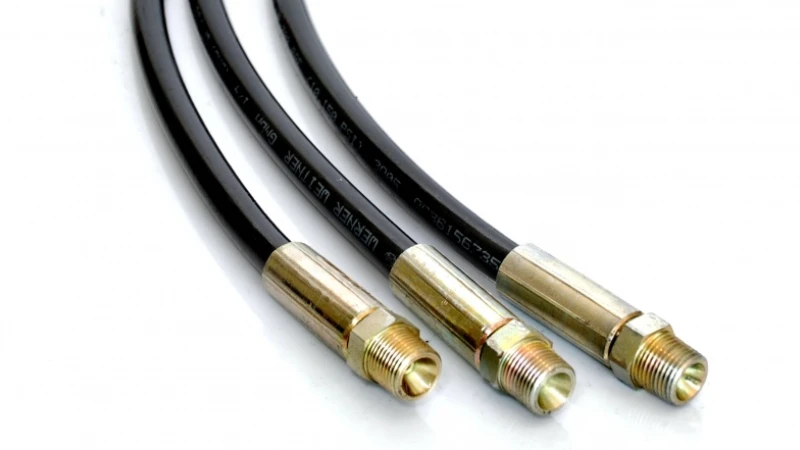
Hydraulic hose assemblies are manufactured through a controlled process that combines hose selection, precision cutting, fitting installation, crimping, cleaning, and pressure testing. Most industrial assemblies are produced according to standards such as SAE J517 and ISO 18752, with working pressures ranging from 70 bar to more than 400 bar depending on construction. Each assembly is measured, inspected, and tested to ensure reliable fluid transfer in construction equipment, mining machines, agricultural systems, and industrial hydraulic units.
Hydraulic hose assembly production starts with selecting the correct hose structure and materials based on operating pressure, temperature, fluid type, and installation conditions. A typical hydraulic hose contains three layers: an inner tube, reinforcement layer, and outer cover. The inner tube is usually made from synthetic rubber such as NBR, which provides resistance against petroleum-based hydraulic oils. The reinforcement layer commonly uses braided steel wire or spiral steel wire to handle internal pressure.
A hydraulic hose designed for industrial equipment may contain one, two, or four layers of steel reinforcement, with pressure ratings commonly ranging from 1,000 psi to more than 6,000 psi depending on the hose construction.
The selection stage determines whether the finished assembly can match the hydraulic system requirements. Low-pressure return lines may use textile-reinforced hoses, while demanding applications require high pressure hydraulic hoses with multiple steel reinforcement layers. In mining and heavy construction equipment, hoses often operate continuously under pressures above 300 bar and temperatures between -40°C and 120°C.
| Hose Type | Reinforcement Structure | Typical Working Pressure | Common Applications |
|---|---|---|---|
| Textile reinforced hose | Fiber braid | 40–100 bar | Low-pressure hydraulic lines |
| Steel wire braided hose | 1–2 steel wire layers | 100–350 bar | Construction machinery |
| Spiral wire hose | 2–6 spiral steel layers | 250–500+ bar | Mining and heavy equipment |
After material selection, manufacturers cut the hose according to the required assembly length. Hydraulic hose cutting machines are designed to create a straight, clean cut without damaging the reinforcement wires. A small dimensional error can affect fitting insertion depth and final assembly performance.
The cutting process usually follows these steps:
-
Measuring the required hose length according to engineering drawings
-
Fixing the hose in a cutting machine
-
Cutting with reinforced blades
-
Removing loose particles from the cut surface
-
Checking the final length tolerance
Many manufacturers maintain length tolerances within ±3 mm for standard assemblies, while specialized applications may require tighter control. In aerospace and industrial automation systems, assembly length accuracy can be controlled within 1% of the specified dimension.
The next stage involves preparing the hose for fitting installation. Some hose designs require skiving, which removes part of the rubber cover so the fitting shell can directly grip the reinforcement layer. Other modern hose systems use no-skive fittings, reducing preparation time and simplifying production.
Skiving requirements depend on hose construction, fitting design, and manufacturer specifications rather than being applied to every hydraulic hose assembly.
During preparation, technicians inspect the hose surface, confirm the correct fitting model, and verify insertion depth. The fitting must enter the hose at the correct position because insufficient insertion can reduce retention strength. Excessive insertion may reduce internal flow area and increase pressure loss.
The fitting installation stage connects the hose body with metal end components. Hydraulic fittings are manufactured from carbon steel, stainless steel, or other corrosion-resistant materials depending on the working environment. Common connection types include JIC, ORFS, BSP, and metric fittings.
The installation process includes:
| Step | Manufacturing Operation | Purpose |
|---|---|---|
| 1 | Fitting selection | Match hose specification and connection type |
| 2 | Hose insertion | Place fitting stem inside hose bore |
| 3 | Position checking | Confirm insertion depth and orientation |
| 4 | Crimp preparation | Prepare assembly for permanent connection |
Once fittings are positioned correctly, the assembly moves to the crimping process. Crimping uses hydraulic pressure to compress the fitting shell around the hose reinforcement. This creates a mechanical connection capable of handling repeated pressure cycles.
Modern crimping machines often use digital control systems that automatically adjust settings according to hose diameter and fitting specifications. A typical crimping tolerance is controlled within approximately ±0.25 mm because even small dimensional changes can affect connection strength.
The crimp diameter is checked after production because it directly affects fitting retention and pressure performance.
During crimping, manufacturers monitor several parameters:
-
Die size selection
-
Crimp diameter
-
Crimp location
-
Compression force
-
Fitting alignment
A poorly adjusted crimping process can cause two common problems. Over-crimping may damage reinforcement wires and reduce flexibility, while under-crimping may allow fitting movement under pressure. Quality systems usually record crimp measurements for each production batch.
After mechanical assembly, hydraulic hoses require cleaning before delivery. Contamination control is important because small particles inside hydraulic systems can damage pumps, valves, and precision actuators.
Cleaning methods include:
-
High-pressure air flushing
-
Cleaning projectiles pushed through the hose bore
-
Solvent cleaning for specific applications
-
Protective end-cap installation
In many industrial applications, cleanliness requirements follow international standards such as ISO 16232 or manufacturer-specific cleanliness specifications. Some hydraulic systems require particle control below hundreds of microns because modern valves contain narrow internal passages.
The finished assembly then enters inspection and testing procedures. Manufacturers perform visual checks, dimensional measurements, and pressure tests before shipment.
Typical inspection items include:
| Inspection Item | Measurement Method |
|---|---|
| Hose length | Measuring tools or automated gauges |
| Fitting angle | Position measurement equipment |
| Crimp diameter | Digital calipers or micrometers |
| Surface condition | Visual inspection |
| Pressure performance | Hydraulic test equipment |
Pressure testing is performed according to hose standards and customer requirements. Proof testing commonly uses pressure levels above the normal working pressure. For example, a hose rated at 350 bar may be tested at higher pressure levels to confirm assembly reliability.
Some manufacturers also perform burst testing on production samples. In these tests, sample assemblies are pressurized until failure to verify that the design meets required safety margins. Testing frequency depends on production volume, customer requirements, and industry regulations.
Quality control systems also include traceability records. Each assembly may receive identification markings containing production date, hose specification, batch number, and manufacturer information.
A traceable production record allows manufacturers to review material batches, machine settings, and inspection results when evaluating long-term service performance.
Packaging is the final manufacturing stage. Finished hydraulic hose assemblies are usually protected with plastic caps or covers to prevent contamination during storage and transportation. For international shipments, manufacturers also consider moisture protection, handling conditions, and storage periods.
Hydraulic hose assembly manufacturing combines material selection, machining accuracy, mechanical joining, and inspection control. From the first hose cut to the final pressure test, each production stage affects the reliability of the finished product. Manufacturers following SAE, ISO, and EN standards typically apply multiple inspection points throughout production, with many facilities recording hundreds of parameters for each production batch.
A well-produced hydraulic hose assembly can provide reliable service for years in demanding environments, including excavators, agricultural machinery, industrial presses, and mobile hydraulic equipment. Proper manufacturing control allows the hose to maintain pressure performance, flexibility, and connection strength throughout its operating life.